
Different Types Of Loads On Structures
When it comes to design of structures for sustainability, there are usually two major factors that we must as structural engineers/designers consider that is Economy and Safety. if the economy is taken seriously with consideration of lesser loads applied on the structure, then the safety of the structure is compromised. if loads applied on the structures are considered the most and applied applied to the structure, then the cost of construction increase. therefore, for a balanced sustainable structure, the estimation of various loads acting on the structure is to calculated precisely. The Eurocodes, Indian standard code IS: 875–1987 and American Standard Code ASCE 7, the Minimum Design Loads for Buildings and Other Structures specifies various design loads for buildings and structures.
The Different Types Of Loads On Structures.
The Loads On Structures can be broadly classified into different categories depending on the direction of their actions on the structure.
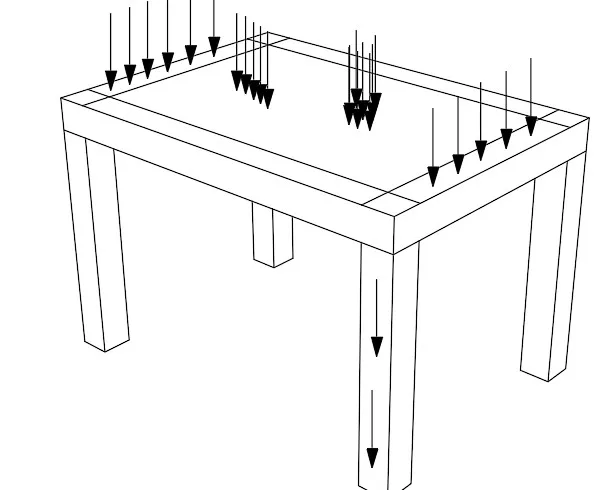
- Vertical loads
- Horizontal loads
- Longitudinal loads, These loads on structures can further be categorized as listed below
- Permanent/Dead loads
- Variable/Live/Imposed loads
- Wind loads
- Seismic loads
- Snow loads
- Rain loads
- Accidental loads/Explosion
-
Permanent/Dead loads
The first vertical load that is considered is dead load. Dead loads can not be moved or stationary loads which are transferred to structure throughout the life span of the structure. permanent load is first of all as a result to self weight of structural members such as beams, columns, slabs, staircase, shear wall, permanent partition walls, fixed permanent equipment and different material weights. It majorly consists of the weight of roofs, beams, walls and column etc. which are actually the permanent parts of the building/structure. The calculation of dead loads of each structure are calculated by the volume of each section and multiplied with the unit weight.
Unit Weight Of Some Common Building Materials
| Sl. No | Material | Weight |
| 1 |
Stone Masonry |
20.4-26.5 kN/m3 |
| 2 |
Brick Masonry |
18.8 kN/m3 |
| 3 |
Plain Cement Concrete |
24 kN/m3 |
| 4 |
Reinforced Cement Concrete |
25kN/m3 |
| 5 |
Timber |
5-8 kN/m3 |
| 6 |
Finishes |
20kN/m3 |
-
Variable/Live/Imposed loads
The second vertical load that is considered in design of a structure is imposed loads or live loads. Live loads are either movable or moving loads with out any acceleration or impact. The loads are assumed to be produced by the intended use or occupancy of the building including weights of movable partitions or furniture etc.. Live loads keeps on changing from time to time. These loads are to be suitably assumed by the designer. It is one of the major load in the design. The minimum values of live loads to be assumed are given in Eurocode 1. It depends upon the intended use of the building. The code gives the values of live loads for the following occupancy classification:
Categories of use
| Category | Specific use | Example |
| A | Areas for domestic and residential activities |
Rooms in residential buildings and houses; bedrooms and wards in hospitals; bedrooms in hotels and hostels kitchens and toilets. |
| B | Office areas | |
| C | Areas where people may congregate (with the exception of areas defined under category A, B and D1)) |
C1: Areas with tables, etc e.g. areas in schools, cafes, restaurants, dining halls, reading rooms, receptions C2: Areas with fixed seats, e.g. areas in churches, theatres or cinemas, conference rooms, lecture halls, assembly halls, waiting rooms, railway waiting rooms.C3: Areas without obstacles for moving people, e.g. areas in museums, exhibition rooms, etc. and access areas in public and administration buildings, hotels, hospitals, railway station forecourts C4:Areas with possible physical activities, e.g. dance halls, gym nastic rooms, stages . C5:Areas susceptible to large crowds, e.g. in buildings for public events like concert halls, sports halls including stands, terraces and access areas and railway platforms. |
| D | Shopping areas | D1: Areas in general retail shops. D2: Areas in department stores. |
| NOTE . | Depending on their anticipated uses, areas likely to be categorized as C2, C3, C4 m ay be categorized as C5 by decision of the client and/or National annex |
The code gives uniformly distributed load as well as concentrated loads. The floor slabs have to be designed to carry either uniformly distributed loads or concentrated loads whichever produce greater stresses in the part under consideration. Since it is unlikely that any one particular time all floors will not be simultaneously carrying maximum loading, the code permits some reduction in imposed loads in designing columns, load-bearing walls, piers supports and foundations. Some of the important values are presented in table below which are the minimum values and wherever necessary more than these values are to be assumed.
Imposed Loads On Structures/floors, balconies and stairs in buildings
| Category of loaded area | qk (KN/m2) | QK (KN/m2) |
| Category A – Floors – Stairs – Balconies |
1,5 to 2,0 2,0 to 4,0 2,5 to 4,0 |
2,0 to 3,0 2,0 to 4,0 2,0 to 3,0 |
| Category B | 2,0 to 3,0 | 1, 5 to 4,5 |
| Category C– C1 – C2 – C3 – C4 – C5 |
2,0 to 3,0 3,0 to 4,0 3,0 to 5,0 4,5 to 5,0 5,0 to 7,5 |
3,0 to 4,0 2,5 to 7,0 (4,0) 4,0 to 7,0 3,5 to 7,0 3,5 to 4,5 |
| Category D-D1 -D2 |
4,0 to 5,0 4,0 to 5,0 |
3,5 to 7,0 (4,0) 3,5 to 7,0 |
-
Wind loads/Loads On Structures
Wind Loads On Structures are the horizontal loads caused by the movement of air relative to earth. Wind load is required to be considered in structural design especially when the height of the building exceeds two times the dimensions transverse to the exposed wind surface. For low rise building say up to four to five stories, the wind load is not critical because the moment of resistance provided by the continuity of floor system to column connection and walls provided between columns are sufficient to accommodate the effect of these forces. Say for building exceeding 5 stories, wind load design must be considered and loads applied according to the wind zones in the specific area provided by the design codes.
The specific Eurocode for wind actions are listed below:
Further in limit state method the factor for design load is reduced to 1.2 (DL+LL+WL) when wind is considered as against the factor of 1.5(DL+LL) when wind is not considered. The horizontal forces exerted by the components of winds is to be kept in mind while designing is the building. The calculation of wind loads depends on the two factors, namely velocity of wind and size of the building. Complete details of calculating wind load on structures are given below (by the IS-875 (Part 3) -1987). Using color code, basic wind pressure ‘Vb’ is shown in a map of India. Designer can pick up the value of Vb depending upon the locality of the building. To get the design wind velocity Vz the following expression shall be used:
Vz = k1.k2.k3.Vb
Where k1 = Risk coefficient k2 = Coefficient based on terrain, height and structure size. k3 = Topography factor The design wind pressure is given by
pz = 0.6 V2z
where pz is in N/m2 at height Z and Vz is in m/sec. Up to a height of 30 m, the wind pressure is considered to act uniformly. Above 30 m height, the wind pressure increases.
-
Seismic loads
These are also known as Earthquake forces, these forces constitute to both vertical and horizontal Loads On Structures or on a building. The total vibration caused by earthquake may be resolved into three mutually perpendicular directions, usually taken as vertical and two horizontal directions. The movement in vertical direction do not cause forces in superstructure to any significant extent. But the horizontal movement of the building at the time of earthquake is to be considered while designing. The buildings experiencing these forces are built on soils in which beneath lies the tectonic plates.
The response of the structure to the ground vibration is a function of the nature of foundation soil, size and mode of construction and the duration and intensity of ground motion. IS 1893– 2014 gives the details of such calculations for structures standing on soils which will not considerably settle or slide appreciably due to earthquake. The seismic accelerations for the design may be arrived at from seismic coefficient, which is defined as the ratio of acceleration due to earthquake and acceleration due to gravity. For monolithic reinforced concrete structures located in the seismic zone 2, and 3 without more than 5 stories high and importance factor less than 1, the seismic forces are not critical.
-
Snow loads
Snow loads constitute to the vertical Loads On Structures. But these types of loads are considered only in the snow fall places, in Europe such places include Tallinn and Estonia, etc. in Africa is mostly found in south Africa, while in India we have Leh Ladakh, Jammu & Kashmir, etc. The IS 875 (part 4) – 1987 deals with snow loads on roofs of the building. The minimum snow load on a roof area or any other area above ground which is subjected to snow accumulation is obtained by the expression
![]()
Where S = Design snow load on plan area of roof. ![]() = Shape coefficient, and S0 = Ground snow load.
= Shape coefficient, and S0 = Ground snow load.
While Eurocode snow loads are listed below
-
Accidental loads Loads On Structures
Accidental loads. As the name suggests, accidental loads result from low probability events such as vehicle or ship impact, explosion, acts of terrorism or earthquake. Although often distinct from the intended function of the structure, such loads are included as a fundamental part of the design process.
When designing an offshore structure, accidental loads that need to be considered are:
- •dropped objects,
- •collision impact,
- •explosions,
- •fire,
- •change of intended pressure difference,
- •load from rare, large breaking wave, and
- •accidental impact from vessel, helicopter or other objects.


